Pages

Thursday, May 31, 2012

Picture Time!

The Whole Project Device

The 3 Gas Sensors

Buzzer on the Left, Temperature Sensor in the Middle, Photo Cell on The Right

RFID Module

LCD Screen and 4 Buttons

LCD Screen and 4 Buttons (again)

Google Code Project Page

We finally got ourselves a Google Code project page for everything. It is located here:- http://code.google.com/p/arduinosensor/

All the wiki and source code will be there as well. Enjoy!

Temperature Sensor & ADC

In our project, we have 5 sensors in all and they are all connected to the ADC of the Teensy. What's an ADC? Read more here.

The cliff notes is that the arduino reads in voltage value from 0v to 5v and it relates this values to a number between 0 to 1023. 0v being 0, 5v being 1023 and everything inbetween is scaled appropriately.

Why the magic number of 1023? The answer: It has only a 10 bit resolution for the ADC. 2^10 = 1024.

For this entry, we will try to calibrate the Temperature Sensor. The data sheet is located here. Our Temperature Sensor is the TMP36 so we shall look at the appropriate section. To calibrate, we take a look at the "Output voltage vs Temperature" Graph.


We can see that line "b" is the sensor we are using and that it is linear. At 0 degrees celcius, it's roughly at 0.5v and at 100 degrees celcius it's at about 1.5v.

By calculating, 0 degrees should give an ADC value of about 102 and a 100 degrees should give 307.

Assuming there's some error of + or - 0.1 volt, the readings can go from 82 to 123 for 0 degrees and 287 to 327 for 100 degrees.

We then did a physical test by putting the sensor near a kettle of boiling water (aka 100 degrees celcius), the reading should an ADC value of 320. When we put the sensor near an ice cube (aka 0 degrees celcius) through a plastic bag, it read 226. The Ice value was expected to be between 82 to 123 but it was so much higher. This could be due to the insulation of the plastic bag preventing an accurate reading.

With this, we know it's linear and that 100 degrees is 320, we can then calculate 0 degrees and hence calibrate it.

Boiling water = 320/1023 = 1.56 volts

Therefore Ice = 1023/5 * (1.56 - 1) = 115 ADC value

This means that 320-115 = 205 ADC values to go from 0 to 100.

1 degree change = 205/100 = 2.05 ADC

Next:-

100 degrees celcius to readings = 320 ADC /2.05 ADC = 156 in temperature
0 degrees celcius to readings = 115 ADC /2.05 ADC = 56 in temperature

We can see it is off by 56, therefore the offset is set to 56. During physical testing, we found that the offset is actually 96 through trial and error.

We can now calibrate it in this method:-
valTemp = taken from ADC
tempOffset = 96
oneDegreeChange = 2.05 ADC

tempCel = (valTemp/oneDegreeChange)-tempOffset;

Cheers!


Tuesday, May 29, 2012

Element14 to the rescue!

Temperature sensor was killed in action. The legs broke off. We needed to get a new one. Where to get good stuff at a good price? Element14!


I called them an hour earlier to place an order. I ordered 2 of TMP36GT9Z a Temperature sensor IC. Costed $1.22 each. Also bought for myself a Desoldering Braid to make my soldering life easier when I make a mistake.

I then went down to collect it on the same day an hour later! Painless ordering and fast!

Oh, did I mention they give Students 8% Discount!

Twitter to Python to Serial Com to Arduino (Part 2)

Twitter has many ways to authenticate a user. For this project, since the device doesn't change we are using "Single-user OAuth". Using that method allows use not to not need to implement the full OAuth token acquisition handshakes.

All you need is:-
  • Consumer key
  • Consumer secret key
  • Access token
  • Access token secret
In order to do so, signup for a new Twitter account that you plan to use for the device. Then head over to https://dev.twitter.com/.

Once there, go to "My Applications" that is listed under the account name and "Create a new application".

Fill up what is needed then head to "Settings" and modify "Application type" to "Read and Write". Then go to "Details" and create an Access Token.

After all is done, take note of the Consumer key, Consumer secret key, Access token and Access token secret.

With this information, you can then tweet directly from python. Here's the code:-

import twitter
api = twitter.Api(consumer_key='key', consumer_secret='key', access_token_key='key', access_token_secret='key')
api.PostUpdate("Hello world from Python!")
And that's it for now!

Updates: Using Timer Interrupts and RFID Profiles

The system consist of the following components:

1) Teensy 2.0 board
2) RFID
3) LCD Display
4) 3 Gas Sensor (details of sensors in previous post)
5) Temperature Sensor
6) Light Sensor
7) 4 Input Buttons
8) Buzzer

 A picture of the current setup
The buttons are labeled as follow (From left to Right, Button 1 - 4)


Interrupts

Interrupts in any micro-controller are necessary and impressive.
Interrupts are asserted periodically say every 2s.
Every 2s (Can be changed) the timer will interrupt the micro-controller and acquire the readings from the 5 different sensors

Current Version

Currently at version 0.2, the system are capable of doing the following.
Button 1 - Start/Stop the cycle process of the LCD screen
Button 2 - Return to the previous display
Button 3 - Go to the next display
Button 4 - Enable/Disable Serial Output (For python to twitter updates)

Profiles

6 User profiles are setup in a separate file
1) Profiles are setup base on the card ID of our Matric Card (Elvin,Ashraf,Boon Tat)
2) Another 3 more tags are setup At the moment, the profiles are only for use with the light sensor.

Our team is still brainstorming on how to calibrate and show useful information using the 3 gas sensor.
The profiles will set a specific threshold and the buzzer will sound if the light intensity exceeds the stipulated value (Tested and proved to be working)

 That's all for the day!

Twitter to Python to Serial Com to Arduino (Part 1)

We planned to have our board tweet it's status update to twitter. In order to do so, we used python and here's how you can do it! We followed this blog entry here. If you are lazy to go there, here's the steps.

Step 1: Install Python. We are using version 2.7.3.

Step 2: Download pyserial and extract the file. To install, go to command prompt / terminal and type "python setup.py install" while inside the extracted folder of the file.

Step 3: Download httplib2 and extract the file. To install, go to command prompt / terminal and type "python setup.py install" while inside the extracted folder of the file.

Step 4: Download simplejson and extract the file. To install, go to command prompt / terminal and type "python setup.py install" while inside the extracted folder of the file.

Step 5: Download setuptools 0.6c11 and install it. For me, I'm using 64 bit Windows 7, so it's a bit tricky. Instead download ez_setup.py and run it in command prompt / terminal by typing "python ez_setup.py".

Step 6: Download a copy of python-oauth2 and extract the file. To install, go to command prompt / terminal and type "python setup.py install" while inside the extracted folder of the file. If you skiped Step 5, this will not work.

And that's it! All the files needed is install.


Edit: I forgot to mention to download Python-Twitter located here. It's the same method as the rest. "python setup.py install"

Let's Talk RFID

The RFID is a cool device. The one that was bought was the SL018 from Stronglink. It's a Mifare card reader and writer.

To use this on the Teensy or Arduino, a person by the name of Marc Boon has already created the necessary library. All you need is to download it here and use it. :)

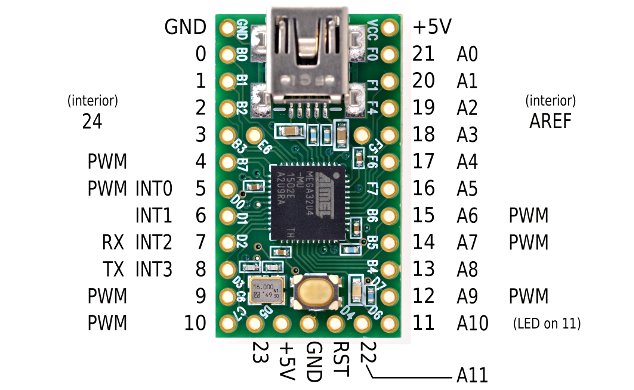
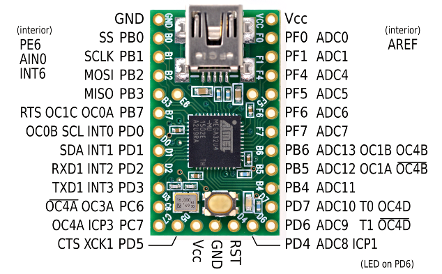
One thing to note is that the SL018 is an I2C device. It communicates via 2 wires. The SDA (data line) and SCL (clock line). If you look at the pinout of the Teensy 2.0 here or above, SCL and SDA is on pin 5 and 6 respectfully. In order to use this easily, you can use the Arduino wire library. Our codes will be up soon so you can take a look at it.

Emergency Parts!

The Temperature sensor was killed in a soldering accident. Time to rush to get a replacement. Nearest place? Element14! They have pretty much everything. :) They were previously called Farnell. Off I go to get the parts. Going to collect them in an hour.

Monday, May 28, 2012

Final Diagram

Here's the final Diagram. You can download the Fritz file here. The Jack module is a Stand in for the SL018 RFID Module from Strong Link. More documentation and code is on the way.

Updated Breadboard Wiring

Here's the wiring! It's kinda messy to see. Made it with Fritzing. I'm going to upload the Fritz file here. In a bit. You can download it here! It's only missing the RFID sensor pins.

Quick Update

Here's a quick update. Proper documentation will be up soon. Here's how the pins are for our board at the moment for the LCD.
This  was done using Fritzing. :)

Sunday, May 27, 2012

Twitter Bot!

Another update! We have a twitter bot for our project at https://twitter.com/#!/robotiam.

Once our device is connected to the computer, it will update periodically it's status and if there is any warnings, it will update that as well.

Cheers!

Updates

Friday, May 25, 2012

Proper Update!

Well, for those who don't know, we are using a Teensy for our project. It's a board that is compatible with the Arduino libraries and hence can use the Arduino IDE. Yayness.

Advantages of Teensy? If you look at the specifications, the Teensy has way more I/O pins that can be used (taken from Teensy website).

SpecificationTeensyTeensy++Arduino Uno
ProcessorATMEGA32U4AT90USB1286ATMEGA328
Flash Memory3225613004832256
RAM Memory256081922048
EEPROM Memory102440961024
Total I/O254620
Analog Inputs1286
PWM (Analog Out)796
USB Port11(serial only)

So that's why Teensy. :)

Next update!

Yesterday we went down to SgBotic and bought mostly sensors. Our shopping list during that trip consits of:-
  • Gas Sensor Breakout Board
  • Carbon Monoxide Sensor - MQ-7
  • Methane CNG Gas Sensor - MQ-4
  • LPG Gas Sensor - MQ-6
  • Mini Photocell
  • Temperature Sensor - TMP36
  • Buzzer - PC Mount 12mm 2.048kHz
Quite a shopping lists.

With all the parts now available, we started on building the boards. Some of the parts we need were already lying around somewhere so we just slapped it on the bread board. Here's the Teensy with a Basic 16x2 Character LCD.


Now that's connected, we added in an RFID module, the HF RFID Module SL018 from StrongLink. It's a pretty cheap RFID reader/writer Module that's cool. It can read MiFare cards.
Here's the picture:-

That's all! Next time, we add the various sensors!


Thursday, May 24, 2012

Quick Update!

We just dropped by the office of SgBotics (Singapore Robotics) and bought some parts! Will list it in the next entry!

Later!

Tuesday, May 22, 2012

Sensors Needed

Here's a list of sensors that we might be implementing in the Envoiroment Sensor Device.

Sensors For our Environment Device:-

  • Mini Photocell  - For light detection
  • Carbon Monoxide Sensor
  • LPG Gas Sensor / Methane CNG Gas Sensor
  • Temperature Sensor
  • Humidity Sensor

New Project!

Ok! So we are planning to stop development of the Arduino Cat device and instead now proceed with creating an Environment Sensor for a house using Arduino.

This device will have various sensors that detect Temperature, Light and more and will be able to control the various devices in a home based on the readings for the sensors.

That's the idea so far. :)

Monday, May 21, 2012

Soldering!

So first up, we would need to solder the Thumb Joystick to the breakout board.This would make prototyping SO much easier. Here's the photos!


Tuesday, May 15, 2012

Parts!

Parts!

Here's some of the parts that I have!


What's there to do? Well, first up, got to solder the Joystick to the breakout board to make it easier for me to use and prototype it. :)

Sunday, May 13, 2012

CAT's Automated Toy (CAT)

So here's the problem:-

Cats have crazy amount of energy and the humans that own the cats are sometimes tired from work to play with them. The solution?

Create an automated toy that a cat can play with! The CAT's Automated Toy (CAT).

The plan is, using an Arduino, create a robot that controls a laser pointer and shoots it around the house. A cat would be interested in the red dot and try to hunt it.

The CAT device will be controlled in the following ways:-
  1. Controlled via computer through USB
  2. Controlled via a controller using a Joystick
  3. Automated controlled using stored movements
(I play too much DrawSomething)
So that's the idea!

Saturday, May 12, 2012

Project Ideas

Ideas for the project:

1) Automated Cat Toy

Using an Arduino, create a device that shoots red lasers around the house. The laser can be controlled via a physical remote or through an application on the computer. It can also automatically shoot the red laser around the house without any control. A pet cat will be interested in following the red dot and chase it everywhere!

Everything will be documented and released.

2) Mssql/Mysql Frontend GUI

To create a frontend to access mssql/mysql database and to release the source code out.

Hello World

Hello world! Welcome to the site!